

Cisco Db9 to Rj45 Console Cable Pinout
Cisco Db9 to Rj45 Console Cable Pinout
This certificate describes how to make a Cisco Console Cablevision (CCC) for Cisco IP Phones.
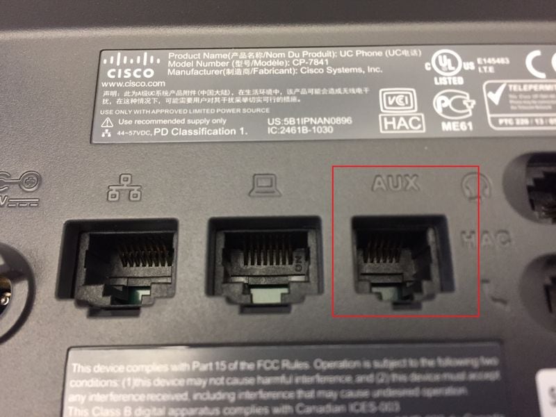
Many Cisco IP Phones take AUX ports on the back that are used to connect Key Expansion Modules (KEM). The RJ-xi port as well serves as a series console port to access the telephone'south concluding. The AUX port of a phone is every bit shown in the image.
Requirements
Cisco recommends that you take cognition of these topics:
- Cisco IP Phones
- Cables for IP networking
- Utilise CCC
Components Used
This certificate is restricted to specific hardware versions.
These models support an RJ-11 serial port.
- 79XX
- 78XX
- 88XX except 8831
The information in this document was created from the devices in a specific lab surround. All of the devices used in this document started with a cleared (default) configuration. If your network is live, ensure that you understand the potential touch of any command.
The standard RJ45 to DB9 apartment CCC pinout is different than the pinout of the RJ11. The table and the two images here brandish the difference between the RJ45 and RJ11 pinout.
| Panel Cable RJ45 (color) | Panel Cablevision RJ45 (pin) | RJ11 Pin |
| red | three | two |
| orange | four | iii |
| green | six | 4 |
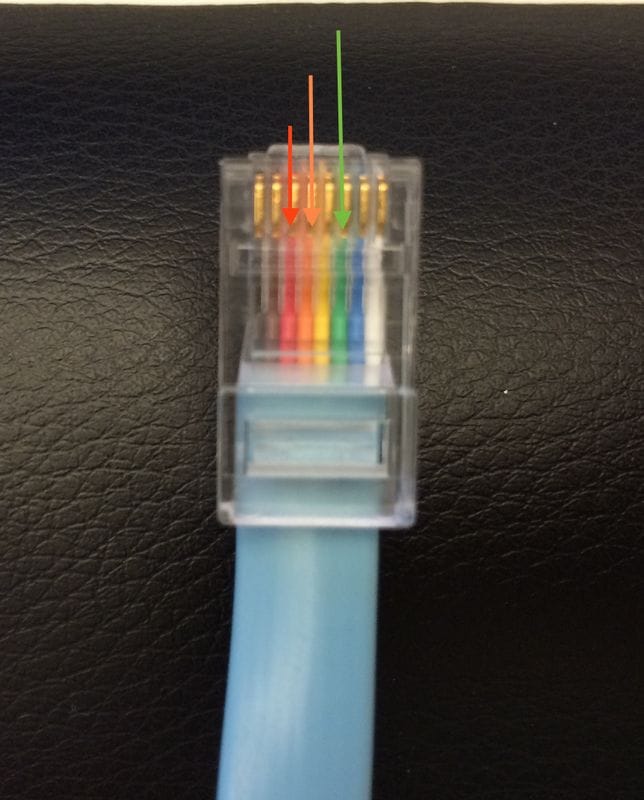 | 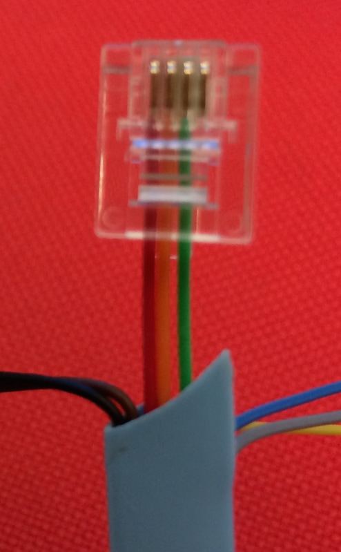 |
| Panel Cable with reddish, orange, and green wires connected to RJ45 pins 3, 4, and 6. Pins iii, iv, and 6 are highlighted for clerity. Console Cable RJ45 side. Pins are counted with the | Console Cable with carmine, orange, and green wires connected to RJ11 pins 2, 3, and four. RJ11 pins are counted with the prune down, from left to right. On a 4-wire RJ11 connector pins ane and 6 are empty. |
Note: It is possible the colors of the wires vary betwixt versions of the CCC. Always verify the RJ45 pin number prior to cut.
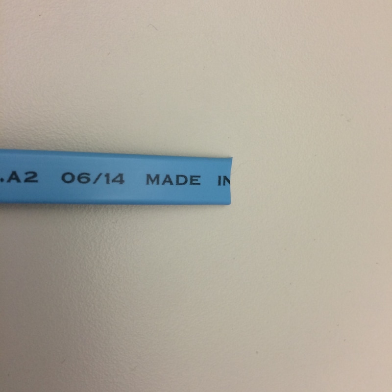
Obtain an RJ45 to DB9 flat CCC and so convert the cablevision an RJ11 to DB9 telephone console cable with the process outlined here. The image hither shows the required cable.
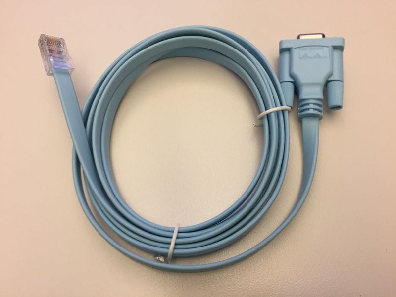
Notation: The part ID for CCC is 72-3383-01 and they are sent with most Cisco devices.
Annotation: Review the section Pinout Explanation before y'all move frontward.
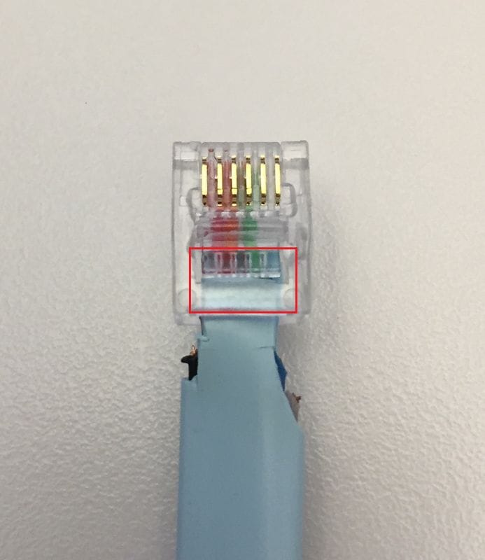
The RJ11 cablevision as shown in the section Pinout Explanation is functional; nonetheless, with just 3 small-scale wires that hold the prune to the cable it can easily interruption. In order to create a cable that is durable, the plastic sheath inside the plastic terminate before crimping. The prototype here shows the blue sheath within the RJ11 prune.

Without modification, the flat console cablevision sheath is likewise wide to fit inside the RJ11 terminal clip. In order to prepare this use a pair of pair of scissors to trim the exterior of the blueish sheath. The detailed steps in this document depict how to properly trim the cable.
Summary Steps
Step i. Remove the RJ45 clip from the CCC
Step two. Trim the blue sheath
Step 3. Remove unnecessary wires
Pace 4. Trim the remaining wires
Step v. Reduce the width of the blue sheath
Step 6. Connect and Crimp the RJ11 Clip
Detailed Steps
Remove RJ45 Prune from CCC
The first step is to cut off the RJ45 terminal from the cable every bit shown in the image.
Trim Blueish Sheath
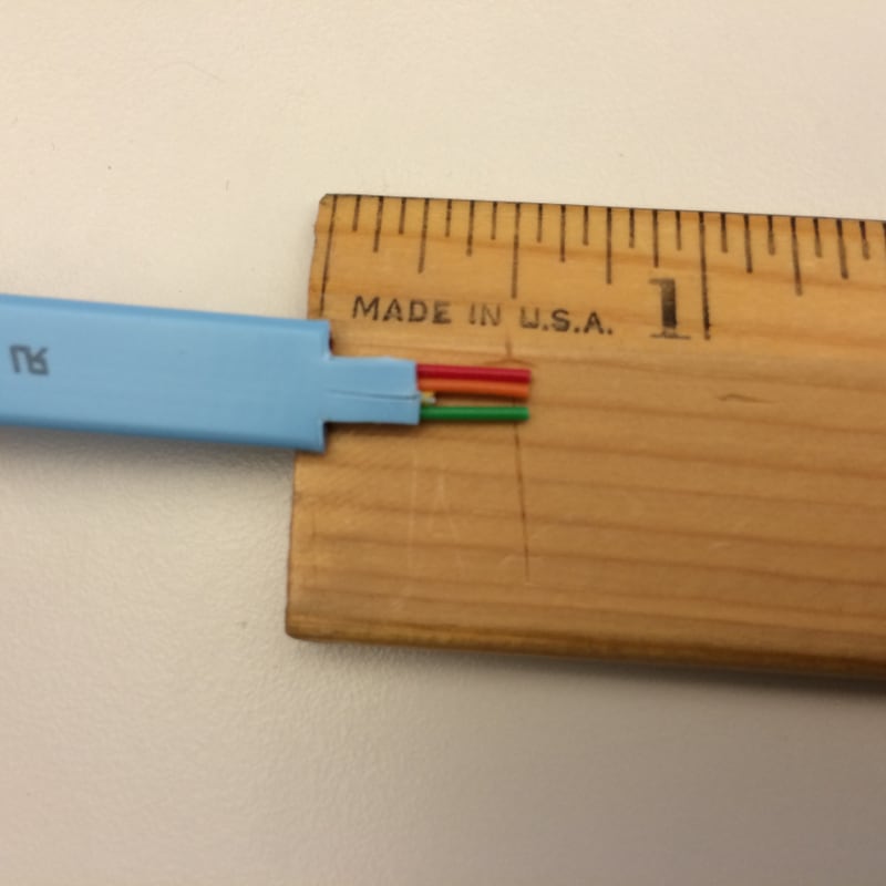
Trim the wire sheath, leaving approximately 0.5 inch (12mm) of wire exposed as shown in the image.
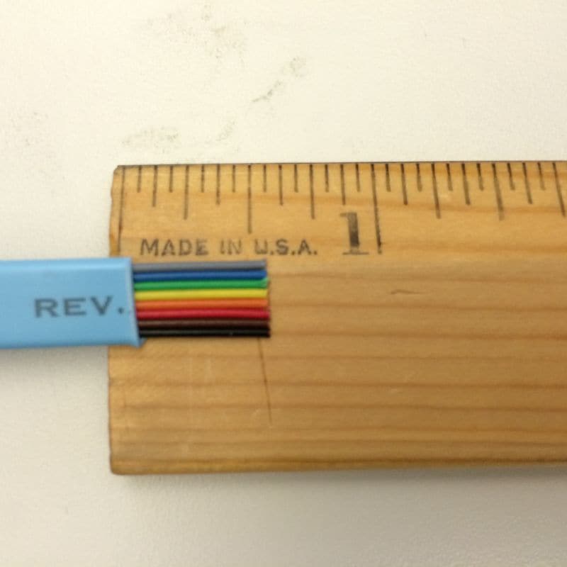
Remove Unnecessary Wires
Remove the unnecessary wires. The remaining wires are red, orange, and light-green as shown in the image.
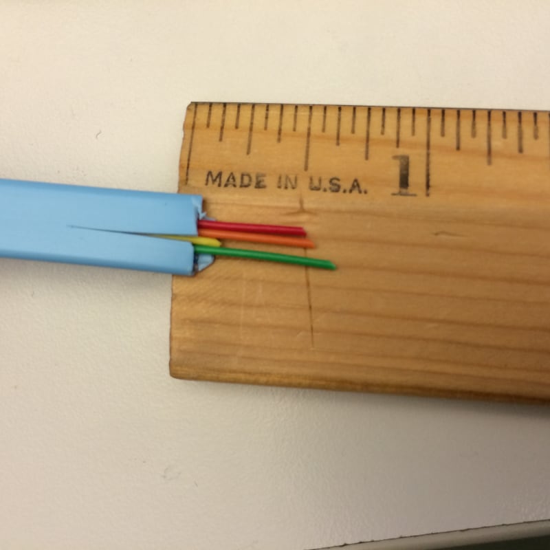
Trim Remaining Wires
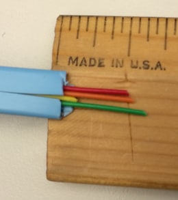
Trim the ends of the cerise, orange, and light-green wires so they are approx 0.25in (6mm) long. Make the cut as square as possible and then that the three wires are exactly the same length as shown in the images.
| | 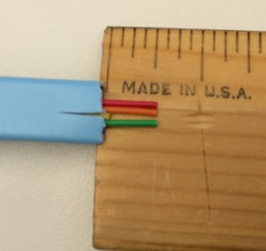 |
| Before Trimming | After Trimming |
Reduce Width Of Blue Sheath
Reduce the width of the sheath in order to allow the sheath access the RJ11 clip. This is washed so the crimp is on the sheath, not the wires. Brand the cut another 0.25in (6mm) down into the sheath as shown in the image.
Connect Crimp RJ11 Prune
The cable is gear up and you need to attach the RJ11 connector and crimp it as shown in the image.
Change the settings of your last awarding. The settings are outlined hither with a screenshot from PuTTy equally an example.
Baud: 115200
Flow Control: None

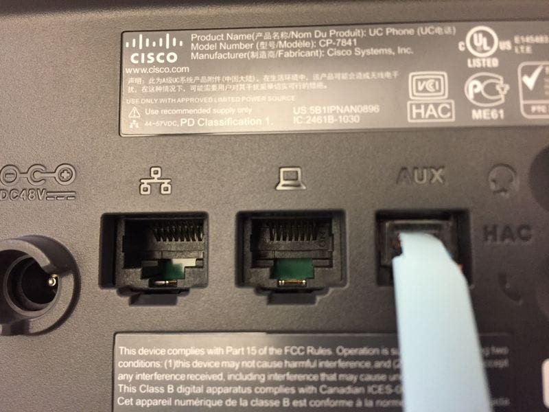
At this bespeak, the cablevision is consummate and ready for testing. Plug the cablevision into the AUX port on the telephone every bit shown in the images and confirm that you tin can connect to the last of the phone without issue.
Annotation: The phone terminal image is from the documentHow To Custom-Brand Cisco IP Telephone Console Cable which covers another way to make a panel cable for Cisco IP Phones.
Cisco Db9 to Rj45 Console Cable Pinout
Posted by: greenitere1946.blogspot.com
0 Response to "Cisco Db9 to Rj45 Console Cable Pinout"
Post a Comment